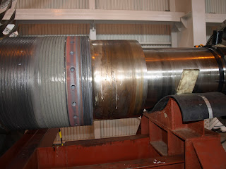
Gbr 1
Dalam catatan kami pernah terjadi failur tersebut di tahun 2002, sehingga bilah fan patah dan menghantam drive shaft gearbox dan merusak beberapa kayu support kontruksi menara pendingin. Akibat kejadian ini diperlukan perbaikan 1 minggu , dan kami harus mengurangi kapasitas pendinginan selama perbaikan itu.
Cooling tower blade spec
Di tahun 2002 pada saat itu wayang windu masih dalam pengelolaan UNOCAL, seperti juga Unocal-gn salak dan Unocal sarula . karena kejadian di wayang windu ini rekan2 di Gn.salak melakukan perbaikan dengan memasang stailess steel plate pada sisi bilah sebagai proteksi,akan tetapi kurang berhasil baik karena ada kejadian copot pada plate nya.
Gbr 2
Di tempat kami yaitu Starenergy geothermal (wayang windu) limited , dilakukan perbaikan dengan cara melapisi kembali bilah ini dengan pelapisan ceramic (ceramic coating). Hal penting yang harus diperhatikan adalah berat bilah setelah di coating tidak melebihi 0.5 kg dari berat awal nya.selain itu juga harus diperhatikan berat terhadap momen nya ( momen weight) karena ini akan berpengaruh terhadap kesetimbangan (balance) ketika sudah dilakukan pemasangan nya kelak.
Setelah penimbangan baik bilah secara keseluruhan maupun momen nya, diberi penomoran agar saat pemasangan kita dapat "mengawinkan" pasangan bilah dengan berat yang kurang lebih sama atau mendekati dengan plus-minus dibawah 500 gram.
Berikut adalah procedure pemasangan kembali bilah fan setelah perbaikan
(Cooling Tower Fan Blades Assembly Procedure ):
1. PURPOSE
This procedure is guidance for assembly of cooling tower fan blade, comply with manufacture manual book and on site blades assembly work practical.
2. SCOPE
This procedure shall apply to Hudson,Tuf Lite II & Tuf Lite III that installing at Cooling Tower Unit I Wayang Windu Power Station.
3. PROCEDURE
A. Preparation
· Conduct safety briefing to all people who involved with the job
· Perform pre-use inspection for tools and lifting gears that will use.
· Visually inspection of blades, fan hub and clamps & bolts from any defect prior to installing
· Ensure the existing permanent marking in blades, fan hub and clamps are clear and visible
· Wear appropriate PPE to perform the job
B. Blades Assembly Work
· Install bushing on the gearbox output shaft
· Put eye bolts on fan hub, and use wire sling to lift fan hub.
· Lift fan hub for 1 meter high, ensure the load are even and safe to be lifted
· Slide fan hub onto the installed bushing in gearbox output shaft carefully
· Tighten the bushing holder bolts even and uniformly
· Remove all attached lifting gear in fan hub
· Tie the blade with web sling, ensure the load are even and safe to be lifted
· Lift the blade to the hub, set the clamp to the blade prior to installing to the hub.
· Slide the blade to the hub horizontally, install clamp bolts and tighten it hand tight only
· Place the blades and clamps refer to existing permanent marking on the hub
· Install the 8 set of blades prior to setting
· Perform the pitch and tracking blade setting work, start with blade no. 1. Use the result of blade no. 1 as a standard or guidance for remain blades
· Continue the setting the blades numerical
· All the setting blades value must be within standard
v Pitch Angle Standard : ± 0.2O Tolerance
v Tracking : Max. 25 mm ( between the highest and lowest blade )
v Clamp bolts torque : 125 ft-lb
v Note : Pitch angle for new and/or rebuild gearbox shall be at 11 degree for the first 500 hrs running. Final setting for the inner cell shall be 12.5 degree (B, C, F, G) and 12 degree for the corner cell (A, D, E, H).
· Install the seal disc cover after setting blades completed
C. Documentation
· Record all setting data’s in CT blade assembly form
· Attach hard copy of setting data’s to related WO and put soft copy in share drive
4. REFERENCE
· Operating & Maintenance Manual vol. 4/41
· Hudson


